Electricity Role Play
Procedures:
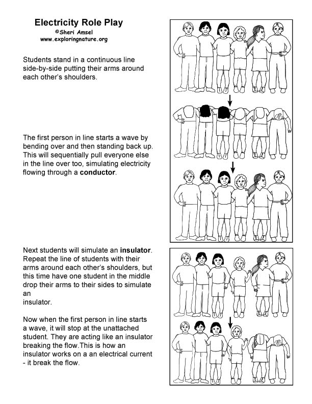
1. Have the students stand in a continuous line side-by-side.
Students will by putting their arms around each other’s shoulders.
2. The first person in line starts a wave by bending over and then standing back up. This will sequentially pull everyone else in the line over too, simulating electricity flowing through a conductor.
4. Next students will simulate an insulator. Repeat the line of students with their arms around each other’s shoulders, but this time have one student in the middle drop their arms to their sides. They should still be next to the other students, but not linked to them. Again, the first person in the line bends over at the waist and stands up. What happens?
4. Discuss with the students what happened this time – how the bending wave stopped at the unattached student. This simulates the effect of an insulator (the unattached student), which is a material that does not allow electricity to easily flow through the it.
5. Point out that a good conductor is a poor insulator and a poor conductor is a good insulator. Brainstorm two lists with the students – one of objects that they think would be good conductors and those that would be good insulators. Ask them how they would find out which was which.
6. After completing your lesson on electricity and circuits, revisit this hypothesis with the students to see if their experiments with insulators and conductors confirmed or refuted their predictions.
About Circuits
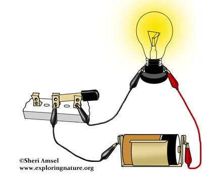
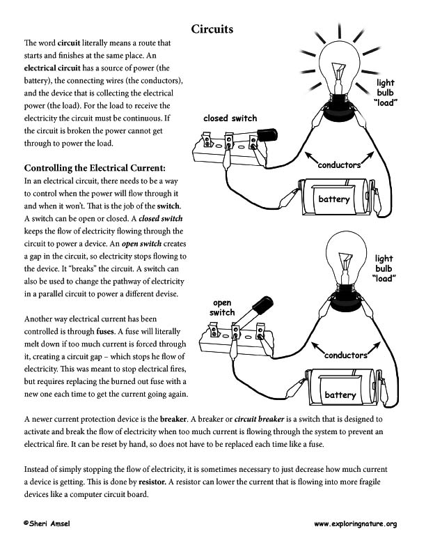
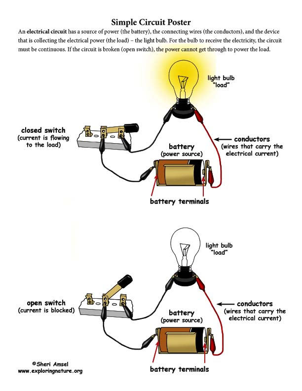
The word circuit literally means a route that starts and finishes at the same place. An electrical circuit has a source of power (the battery), the connecting wires (the conductors), and the device that is collecting the electrical power (the load). For the load to receive the electricity the circuit must be continuous. If the circuit is broken the power cannot get through to power the load.
Controlling the Electrical Current:
In an electrical circuit, there needs to be a way to control when the power will flow through it and when it won’t. That is the job of the switch. A switch can be open or closed. A closed switch keeps the flow of electricity flowing through the circuit to power a device. An open switch creates a gap in the circuit, so electricity stops flowing to the device. It “breaks” the circuit. A switch can also be used to change the pathway of electricity in a parallel circuit to power a different devise.
Another way electrical current has been controlled is through fuses. A fuse will literally melt down if too much current is forced through it, creating a circuit gap – which stops he flow of electricity. This was meant to stop electrical fires, but requires replacing the burned out fuse with a
new one each time to get the current going again.
A newer current protection device is the breaker. A breaker or circuit breaker is a switch that is designed to activate and break the flow of electricity when too much current is flowing through the system to prevent an electrical fire. It can be reset by hand, so does not have to be replaced each time like a fuse.
Instead of simply stopping the flow of electricity, it is sometimes necessary to just decrease how much current a device is getting. This is done by resistor. A resistor can lower the current that is flowing into more fragile devices like a computer circuit board.
Types of Circuits
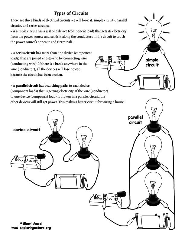
There are three kinds of electrical circuits we will look at: simple circuits, parallel circuits, and series circuits.
• A simple circuit has a just one device (component load) that gets its electricity from the power source and sends it along the conductors in the circuit to touch the power source’s opposite end (terminal).
• A series circuit has more than one device (component loads) that are joined end-to-end by connecting wire (conducting wire). If there is a break anywhere in the wire (conductor), all the devices will lose power, because the circuit has been broken.
• A parallel circuit has branching paths to each device (component loads) that is getting electricity. If the wire (conductor) to one device (component load) is broken in a parallel circuit, the other devices will still get power. This makes a better circuit for wiring a house.
Simple Circuit Making Activity
Goals:
1. Learn about the parts of a circuit.
2. Understand how the flow of electrical current moves between the power source and device and the role of the conductors.
3. Learn about which materials conduct electricty and which do not.
Materials for Each Group:
• 1 D-cell or C-cell battery
• 4 strips of aluminum foil, about 1cm (1/2 inch) wide and 12-15 cm (5-6 in.)
• 1 flashlight bulb (1.5 - 3-volt)
• sturdy rubber band
• 1 alligator clip for each group
• 1 square card board (can be cut from a cereal box)
• scissors
• tape
• penny
• pencil
• plastic pen
• metal pen or spoon
Directions:
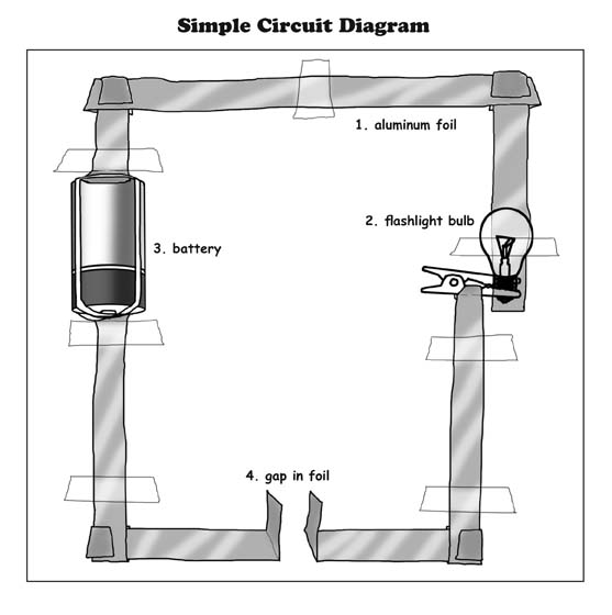
1. Each group should layout their 4 strips of tinfoil in a square and fold the corners together (see diagram).
2. Using your scissors, cut the left side strip in the middle, fold up each end into a flap and fit the battery between the flaps. Tape the tin foil in place (see diagram).
3. Using the rubber band, secure the folded ends of the tin foil against the battery terminals at each end.
4. Now cut the bottom strip in the middle and fold up the flaps. This represents an open switch.
5. Now cut the right strip in the middle. Tape down the top end (see diagram).
6. Pinch the metal bottom of the bulb securely in the alligator clip. Then wrap the flap of the bottom end of the right strip around the alligator clip (see diagram).
7. Set the bulb onto the top end (see diagram).
8. Using your fingers pinch the two flaps of the bottom strip together. This will close the switch.
9. What happens? Explain this in terms of an active electrical circuit on the data sheet. (Data Sheet in PDF below.)
10. Connect the bottom flaps through each of the test conductors (penny, pencil, plastic pen, metal pen or spoon) and record whether they are conductors.
11. Label the Simple Circuit Diagram with the proper names of each part of the circuit. (Labeling Page in PDF below.)
Test their knowledge of circuits with the:
Circuits - Multiple Choice Quiz
Circuits – Vocabulary Assessment Quiz
When you research information you must cite the reference. Citing for websites is different from citing from books, magazines and periodicals. The style of citing shown here is from the MLA Style Citations (Modern Language Association).
When citing a WEBSITE the general format is as follows.
Author Last Name, First Name(s). "Title: Subtitle of Part of Web Page, if appropriate." Title: Subtitle: Section of Page if appropriate. Sponsoring/Publishing Agency, If Given. Additional significant descriptive information. Date of Electronic Publication or other Date, such as Last Updated. Day Month Year of access < URL >.
Amsel, Sheri. "Circuits Unit (Complete)" Exploring Nature Educational Resource ©2005-2024. December 13, 2024
< http://www.exploringnature.org/db/view/1827 >